Worm face gear with cylindrical pinion.
Stepan Lunin. 03/03/2003
The author applied Direct Digital Simulation method for analyses of worm face gear with cylindrical pinion:
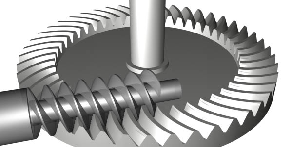
Manufacturing of worm face gear similar to a regular worm gear and normally no special manufacturing or inspection equipment required. Localization of the tooth contact can be done by modifying the gear cutter or the pinion. The advantage of a worm face gear versus a regular worm gear is higher driving efficiency and higher strength. The worm face gear can be designed self-locking or back derivable. It is common to design worm face gear with different pressure angle on the opposite sides of the tooth. Lower pressure angle on the front of the pinion helps to avoid undercut on the front side of the pinion thread. The high-pressure angle on the backside of the pinion prevents undercut on the gear tooth. However the amount of undercuts always depend on design of the gear set. It is possible to design a face worm gear set with equal pressure angles on both sides of the tooth like it is shown on the 3-dimentional model above.
The author has developed the following tools for face worm gear analyses:
1. Calculation of 3D geometry of the gear and pinion tooth surface. Generating CAD model for CMM inspection or for injection molding tools machining on CNC
2. Computer simulation of the gear mesh with animated contact pattern, sliding velocities and transmission error
3. Calculation of the gear cutting tool geometry and gear cutting machine summaries
4. Calculation of undercut areas on both flanks on gear and pinion teeth.
5. Generation data file for finite element analyses
6. Calculation of cutting tools modifications and crowning for localization of the contact pattern.
The author used the AutoLIST routine below for a simple visualisation of cutting the worm face gear.
(defun w ()
(setq n nil)
(setq n (getreal " Number of teethon gear <21>:"))
(if (= n nil) (setq n 21.0))
(setq k nil)
(setq k (getreal " Number of teeth on pinion <1>:"))
(if (= k nil) (setq k 1.0))
(setq lead nil)
(setq lead (getreal " Lead of the worm <11.899 mm>:"))
(if (= lead nil) (setq lead 11.899))
;;;step of pinion rotation
(setq dfi nil)
(setq dfi (getreal "\n Step of pinion rotation <30 degrees>:"))
(if (= dfi nil) (setq dfi 30.0))
(setq dfi (/ (* pi dfi) 180.0))
(setq dfi (* dfi (- 0.0 1.0)))
;;;Step of pinion movement
(setq dz (/ (* dfi lead) 2.0 PI))
;;;step of gear rotation
(setq dal (* (/ dfi n) k))
(setq gear (entsel "\n Select gear."))
(setq pin (entsel "\n Select pinion."))
(getreal "stop")
(setq al 0)
(while (< al (/ pi 3.0))
(command "copy" pin "" (list 0 0) (list 0 0))
(command "subtract" gear "" (entlast) "")
;;;move the pinion
(command "move" pin "" (list 0.0 0.0 0.0) (list 0 0 (- 0.0 dz)))
;;;rotate the gear
(command "ucs" "y" -90)
(command "rotate" gear "" (list 0.0 0.0) (list (cos dal) (sin dal)))
(command "ucs" "w")
(setq al (+ dal al))
)
)
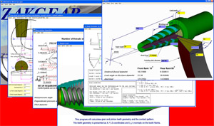
The pictures below are the output of running the AutoLISP program with AutoCAD.

The picture shows the face view on the gear. White circules are the gear tooth face and the red lines are the generating surface of the cutting tool. The idea of the presentation is to show step by step the manufacturing process of the gears. The red cutter surface moves and the white gear blank rotates.
Each step the red cutter takes some material out of the white gear blank. The same happens during real cutting. The cutter does not have infinite quantity of the cutting blades. Each blade creates a cutting mark. There are the cutting marks on this computer model as well.
The CAD simulation shows undercut areas on the both flanks of the gear. The model on the picture is in wire frame so you are looking at the both flanks in the same time.
The digital analyses originally proposed by the author make manufacturing and design of worm face cost effective and more productive. The gear tooth surface and the contact pattern can be predicted on a 3-dimentional digital models before the prototypes are manufactured. The 3-dimentional model of the worm face gear can be used for manufacturing of the gears in CNC machines. It can be less expansive for some medium quality applications or for plastic gears.
 Click here for worm face gear with tapered pinion.
Home page: www.zakgear.com