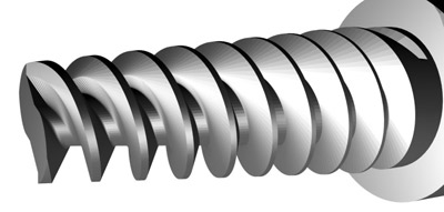
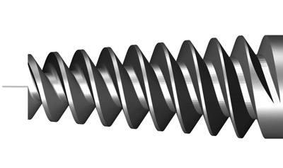
Worm face gear with tapered pinion.
By Stepan Lunin. 02/02/2002
|
|
|
|
|
|
Worm face gear with tapered pinion.
By Stepan Lunin. 02/02/2002
|
|
|
|
|
|
Computerized simulation of tooth geometry, manufacturing of gears as well as the gear mesh using a discrete computational tool has been done by the author for two decades. 3D visualization allows to examine geometry of the tooth surfaces as well as contact pattern and transmission error. The best correlation between 3D computer modeling and manufacturing process has been found at The Gear Research Laboratory directed by professor Veniamin Golgfarb in Izevsk, Russia. The Gear Research Laboratory works closely with a local production facility where the gears are manufactured.
The author has extended development in geometrical and manufacturing area of the gear. Different geometry and manufacturing processes were simulated on computerized 3-dimentional models of the gears. A number of computer programs have been written for true and realistic 3-dimentional-geometry simulation of the gears.
Pinion of the presented gear set has an involute geometry. It can be manufacturing by different methods including but not limited by thread grinning, milling, hobbing, rolling and whirling. Manufacturing of the face gear is more complex, but it can be done on a regular hobbing machine with manor adjustments. The hob cutter has to have similar to the pinion form. Localization of the contact pattern can be done by different methods: gear cutter modification, pinion cutter modification or adjustment of the pinion cutting tool pass. It is a mistake to use an oversized gear cutter for localization of the contact pattern. Normally the oversized cutters are proposed by gear cutting shops as a simple way to localize the contact pattern and decrease sensitivity of the gear set for misalignments. The author had experience with different suppliers that used oversized cutters to cut the gears. Every time computer simulation showed incorrect location of the contact. Normally the supplier conducts a rolling test of the gear set to show the tooth contact. But it is always very difficult to see the contact area on a face gear with small teeth. Transmission error is normally very small and the gear set is very quiet even with incorrect contact because of a large number of the teeth participate in the contact in the same time. The worm face gear drive has many advantages like higher efficiency, lower noise, higher strength and more. In most of the situations even poor manufacturing worm face gear set will be working as good or a little better than a regular worm gear set. But in applications with high requirements the design and manufacturing has to be done with correct understanding of the geometry of the gear set. Computerized 3-dimentional of the geometry and the contact would be the best currently available tool for that.
One disadvantage of the pinion geometry is variable tip width of the thread. The variable tip width limits the design options. For example the tapered angle has to be small so the tip on the large diameter does not get sharp.
About backlash.
The backlash can be adjusted only on tapered pinion by moving the pinion along its axis. Only axial motion of the pinion does not change the contact pattern. Adjustment of the backlash on gears with cylindrical pinion is impossible without braking the contact. Normally the backlash on the worm face gear can not be better than on a regular worm gear. A designer should not use a worm face gear because of possible low backlash. The worm face gear will always have a higher run out than a regular worm gear. The run out and the profile angle normally determine required amount of the backlash. Higher profile angle and higher run out need higher backlash. Unfortunately the profile angle on the worm face gear can not be small because of undercuts. Small profile angle on the pinion will make an undercut on the front flank of the pinion. A small profile angle on the backside of the pinion will generate an undercut on the gear tooth. The benefit of the regular worm gear is possibility to use a small profile angle. It is even possible to make a worm gear with 0-pressure angle.
Transmitting high power.
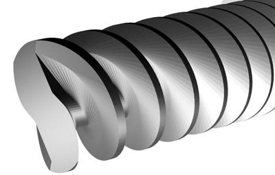
It looks like the gear set can transmit higher power because of many teeth are in the contact in the same time. Designers should not to expect much from the gears because the manufacturing process in most suppliers does not take an advantage of all benefits of the worm face gear set. Detailed 3-dimentional-computer simulation of the tooth geometry is a necessary tool for manufacturing a stronger worm face gear set. The contact ratio is really high but it is not always good for transmitting of high power. In general gear practice lower contact ratio transmit more power. The reason of that are smaller weak teeth on high contact ratio gears and large strong teeth on small contact ratio gears. The load is not distributed evenly between the large quantity of small teeth on high contact ratio gear so some teeth are overloaded. Also most manufactures do not produce high accuracy gears. The pinion can be ground but it is impossible to use grinding for gear teeth finishing. The gear-cutting tool is just as small as the pinion. It deflects during cutting because its small diameter and it has very few cutting edges. Gear cutting ratio has to be the same as the gear set ratio so it is impossible to have a hunting ratio for cutting if the gear set does not have it. High contact ratio is good for transmission accuracy but it is not always good for the gear strength. There is another big problem with the gear. Most of them have undercut of the gear and pinion tooth surfaces. Visually they look good but the real contact area has been decreased by the gear and pinion undercuts. The author’s 3-d computer simulations of undercut are presented below.
Ratios.
The ratios are limited because of the realistic pinion would have 1,2 or 3 threads. The problem is the gear cutter. The gear cutter has to have the same geometry that the pinion so it has to have the same number of the threads. Unlike manufacturing of worm gears an oversized cutter can not be used. This fact was tested a number of time by the author on 3-dimentional computerized models of the gears. The cutter has a limit in its lead angle (some 25 degrees) so the pinion has the same limit. Hunting ratio is very desirable during the gear cutting for decreasing spacing error. In our case it is very important because the small and flexible cutting tool. The hunting ratio can be achieved only with 1 or 3 thread cutter. So good gear set ratio can be for example: 44:3 or 67:3 but not 66:3 or 72:3.
Re. Easy to mold.
The molding process is as easy as molding of hypod, HRH, crown or spiral bevel gears. Unfortunately the gear manufactures can not provide the computer models of the gears. It does not allow designing a mold correctly. Plastic shrinks. It has to be taken in to account. Using oversized gear and pinion as electrodes do not solve the problem because it is impossible to cut the gear that is oversized in the same directions those plastic shrinks. 3D cad models have to be used for mold design and inspection. CAD model can be created from a master par by mapping on CMM. However such of model has low accuracy. Advanced computerized 3-dimentional tools have to be used to create 3D CAD files of the theoretical gears.
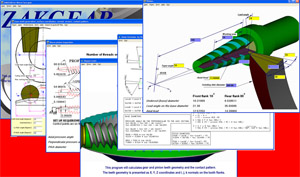
Re. Pressure angles on front and rear part of the pinion.
The gears almost always have two different pressure angles on the same tooth. The front working angle is usually about 10 and rear angle is 30 degrees. Different pressure angles are not a very good solution for the drive that has to rotate in both directions. However it is possible to design and manufacture the worm face gear with equal profile angle with an extensive help of the advanced computerized 3-d CAD tool.
Re. TCA and contact pattern developing.
The new 3-d CAD method allows to simulate gear and pinion cutting process, show the contact pattern, calculate sliding, rolling and cutting velocities. Digital investigation of different options for the contact pattern development results:
- It is impossible to achieve a localized contact pattern by using oversized gear cuter.
- The localized contact pattern can be achieved by the modified cutter or by modified pinion.
- The contact pattern is very sensitive for all of possible misalignment but not for axial of pinion.
The tooth profile on the pinion in section perpendicular to the axis is usually involute.
However other profiles can be used. The design does not require having 90 degrees angle between gear and pinion axis.
The surface of pinion tooth is a helical surface.
The gear tooth surface is more complicated for mathematical description. 3-d CAD method can be used for 3D-gear tooth geometry calculation. There are some interesting facts about the gear tooth surface. There is a section of the gear tooth surface that is an involute. This section is perpendicular to the gear axis and locates on a certain distance from the pinion axis. The distance from the pinion axis depends on the pressure angles and determines as a base radius of the pinion involute section. The gear tooth has to be tall enough in order to have this involute section on it.
Inspection of the gear tooth can be done on CMM against a digital master. The tooth form of the pinion allows some basic inspections such as profile and lead. It can be done on an involute-measuring machine.