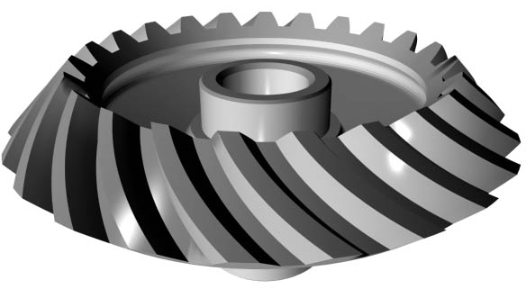
 Complex form of gear cutter.This complex tooth form was proposed by Dr. Zhuravlev G.A. We have developed practical solutions for manufacturing and inspection of the complex tooth geometry in 1986-1992 at MIL Helicopter in Moscow, Russia. DDS method was extensively used for 3-dimensional modeling of the tooth geometry and bearing contact.
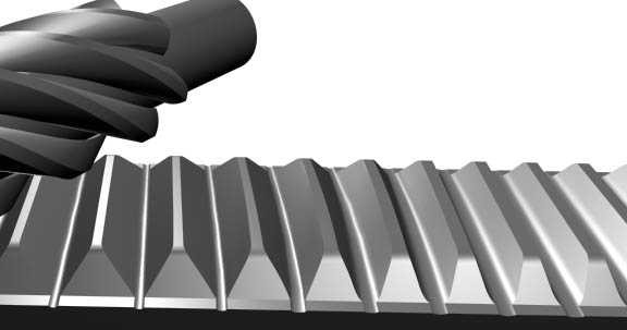
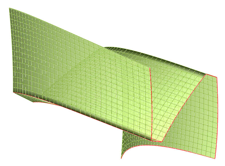
 This is an output from the author’s computer program that simulates 3-dimentional complex tooth geometry from the cutter presented on the picture above.
AVI animation 0.2Mb.
This is an output from the author’s computer program that simulates 3-dimentional complex tooth geometry from the cutter presented on the picture above.
AVI animation 0.2Mb.
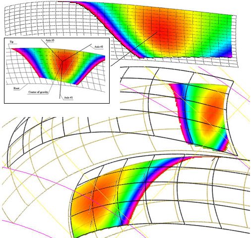
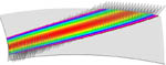
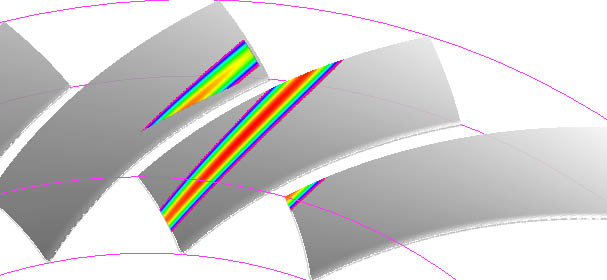
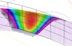
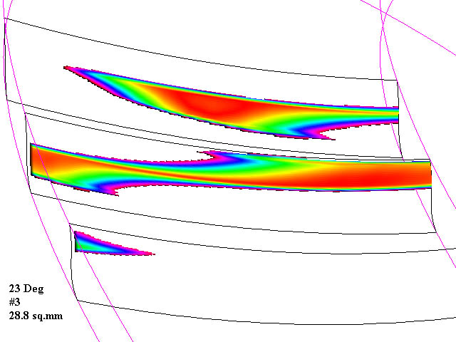
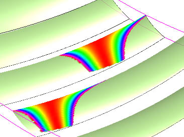
 3-dimentional model of the bearing contact for the gear tooth geometry presented on pictures #1 and #2. The rainbow colors show distances between mating tooth surfaces. The black short lines are the 3-dimentional sliding vectors. The author used the sliding vectors for calculation of the integrated driving efficiency. The direction of sliding and friction is calculated on each point of the 3-d model. Then it is integrated in to driving efficiency.
AVI animation 0.3Mb.
3-dimentional model of the bearing contact for the gear tooth geometry presented on pictures #1 and #2. The rainbow colors show distances between mating tooth surfaces. The black short lines are the 3-dimentional sliding vectors. The author used the sliding vectors for calculation of the integrated driving efficiency. The direction of sliding and friction is calculated on each point of the 3-d model. Then it is integrated in to driving efficiency.
AVI animation 0.3Mb.
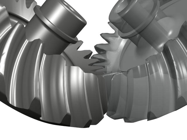
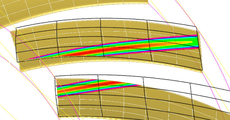
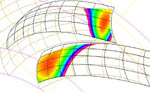
 Reverse engineered tooth contact taken from a real spiral Bevel gear set.The reverse engineering program allows to see the tooth contact without mating the real gears. The program uses the only 3-dimentional mapping of the real gear tooth surfaces. The image is not looking very good because of the manufacturing deviations on the real gear tooth surfaces. This programming module replaces an expensive single flank contact inspection machine on a manufacturing floor.
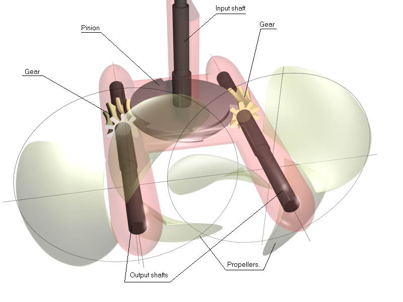 Marine application for ultra globoid gear. It is a sample application of an extreme Globoid (Hourglass) gear. The driving efficiency would not be as high as with spiral bevel gear. But the compact design decreases the hydrodynamic drag of the submerged gear housing. The combined propulsion efficiency is higher than with similar spiral bevel gear design.
 Example of 3-d modeling of hypoid gear in AutoCAD.The DDS method can be used with simple programming of standard CAD software. This image shows a virtual spiral bevel gear cutting machine created in AutoCAD.
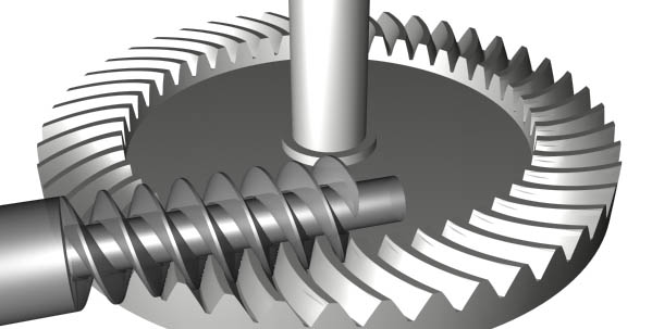
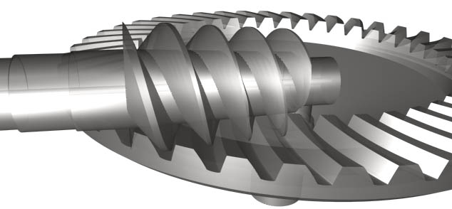
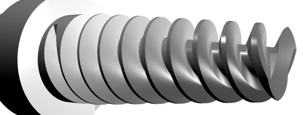
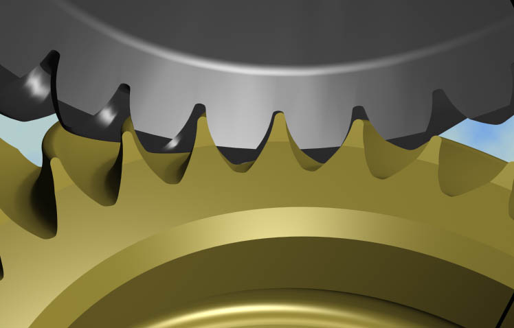
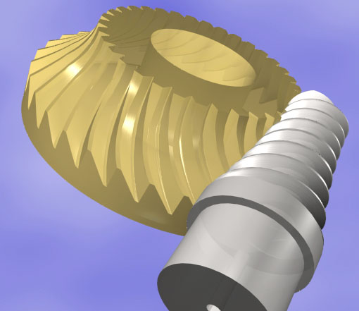
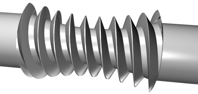 Globoid or Hourglass pinion. The globoid gear set has higher driving efficiency and higher load capacity than a worm gear set. But the manufacturing may be more complex. But in same application the cost can be significantly decrease. Unlike a worm gear the only a half of the gear is working when it rotates one direction. It is the same on the pinion. That makes it possible to mold plastic globoid gears.
 Unlike most of the researchers the author investigates Wildhaber-Novikov tooth contact in 3-dimentional space. The image shows different positions of the Novikov tooth contact for a rotating gear set.
AVI animation 0.4Mb.
Unlike most of the researchers the author investigates Wildhaber-Novikov tooth contact in 3-dimentional space. The image shows different positions of the Novikov tooth contact for a rotating gear set.
AVI animation 0.4Mb.
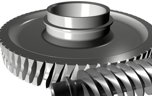
 Worm face gear has higher driving efficiency than a worm gear. It is also more compact. The common problem in manufacturing is cutter design and modification of the tooth surface to make the gears not sensitive for the manufacturing errors. The inspection of the finished gear is also a common problem because of the difficulties with gear tooth CAD modeling. The author has an extensive experience in manufacturing and CAD modeling of the worm face gears based on DDS method. The gears can be cut by a worm cutter and then inspected against a DDS 3-d model on CMM. The tool for injection molded plastic gears can be manufactured on CNN from a DDS CAD model without involving expensive gear cutting tools and machines.
 Tooth cutting simulation of worm face gear.The DDS method provides very detailed visualization of the gear cutting. This example shows common areas of undercut and cutting marks on a worm face gear tooth.
 High ratio hypoid gear model has been simulated by the author in 1988 as a proposal for a tail helicopter rotor drive. However the evaluation of the driving efficiency showed that on high ratio the gear set becomes not reversible (not backdrivable). Driving efficiency was improved by using advanced tooth profiles. But it did not go in production because of poor manufacturing capabilities in 1990.
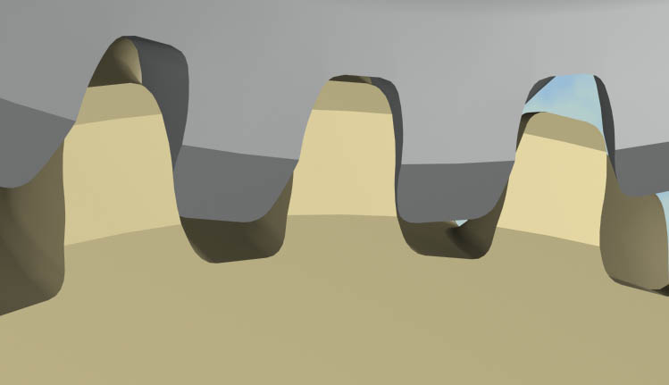
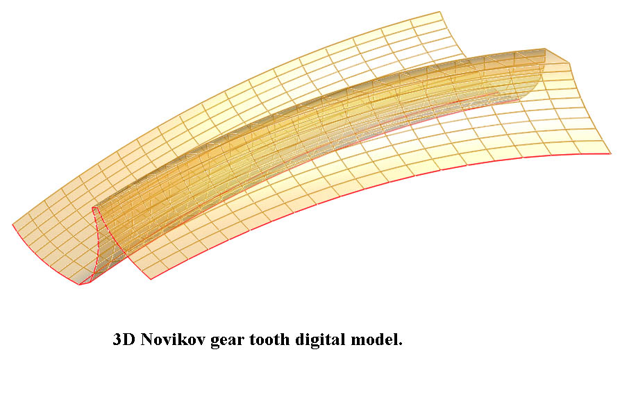
 Ideal Novikov tooth contact. Concave and convex profiles have the same radiuses of curvature. This 3-dimentional simulation shows how would the contact look like it to mesh Novokov gears without crowning on profile. The original idea of the Novikov gear incorporated a small difference of the radiuses for decreasing of the contact stresses. Smaller the difference – smaller the stress? Would be the maximum contact stress unlimited when the radiuses are the same? The classic Hertz theory says yes. But in reality nobody made a strong Novikov gear yet. The 3-dimentional simulation explains it. The contact pattern really spreads across the tooth but it is still very short along the tooth.
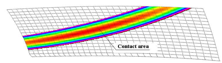 Spiral Bevel tooth contact. This contact is not what one normally sees on a spiral bevel rolling tester. The rolling tester shows a combined tooth contact. More correct it shows a footstep. But it does not show the way it was generated. The DDS software for spiral bevel gears shows the tooth contact in its development.
AVI animation 0.4Mb.
Spiral Bevel tooth contact. This contact is not what one normally sees on a spiral bevel rolling tester. The rolling tester shows a combined tooth contact. More correct it shows a footstep. But it does not show the way it was generated. The DDS software for spiral bevel gears shows the tooth contact in its development.
AVI animation 0.4Mb.
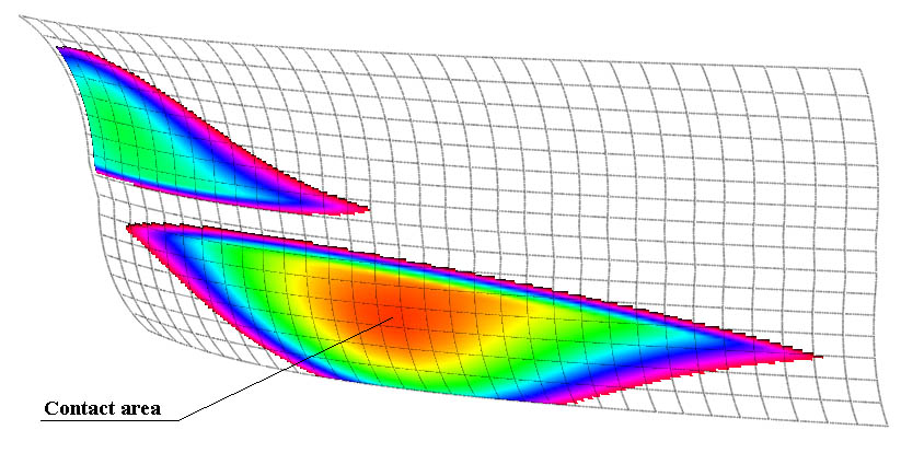
 Spiral Bevel tooth contact and sliding. Calculating of correct sliding in 3-dimentional space is very important for driving efficiency calculation. The integrated efficiency calculation program takes into account every point in the tooth surface that contributes to the overall driving efficiency. The detailed simulation allows predicting and comparing the driving efficiency for different tooth forms and different cutting machine settings.
AVI animation 0.6Mb.
Spiral Bevel tooth contact and sliding. Calculating of correct sliding in 3-dimentional space is very important for driving efficiency calculation. The integrated efficiency calculation program takes into account every point in the tooth surface that contributes to the overall driving efficiency. The detailed simulation allows predicting and comparing the driving efficiency for different tooth forms and different cutting machine settings.
AVI animation 0.6Mb.
 3-d model of tooth contact for (2).
 3-d model of tooth contact for (2).
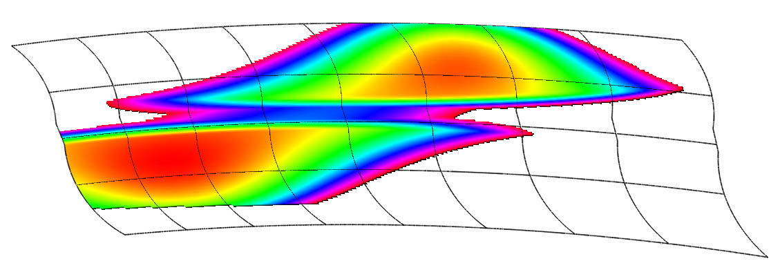
 This is a 3-dimentional computer simulation of a classic Wildhaver-Novikov tooth contact. The mating profiles have different radiuses of curvatures. In many published papers one can read about an ellipse of the contact. Some authors even discuss the size of the ellipse axis. We do not confirm the elliptical shape of the tooth contact on Novokov gears and on any other gears. Our first objection is addressed to using word ellipse for describing a complex 3-dimentional surface. What we can see on an exact 3-d model of mating teeth does not even look like an ellipse.
AVI animation 0.7Mb.
This is a 3-dimentional computer simulation of a classic Wildhaver-Novikov tooth contact. The mating profiles have different radiuses of curvatures. In many published papers one can read about an ellipse of the contact. Some authors even discuss the size of the ellipse axis. We do not confirm the elliptical shape of the tooth contact on Novokov gears and on any other gears. Our first objection is addressed to using word ellipse for describing a complex 3-dimentional surface. What we can see on an exact 3-d model of mating teeth does not even look like an ellipse.
AVI animation 0.7Mb.
 Palloid gear.
 DDS method was used for developing of software code for variable ratio rack geometry. The advance capabilities of the DDS method allowed testing different tooth forms on the generating pinion. It helps to increase the range of the ratio and increase the load capacity in the same time. The other important achievement is a low-pressure angle. The low-pressure angle decreases the separation of the rack and the pinion.
 Calculation of sliding and contact pressure in each point of the gear tooth surface may be extremely important. It provides valuable data for development low noise and high efficiency drive.
 This spiral bevel gear set with not involute tooth form has been cut on DDS bases computer code and visualized with a help of OpenGL platform. The DDS tool helps the author to create the highest resolution digital gear models since the beginning of development of the method in 80’s.
AVI animation 0.7Mb.
 It is important to see the contact action on all participating teeth. The contact ratio is not a constant number in the real gear action. It is changing permanently depending on the combined area of contact on all teeth.
AVI animation 0.2Mb.
It is important to see the contact action on all participating teeth. The contact ratio is not a constant number in the real gear action. It is changing permanently depending on the combined area of contact on all teeth.
AVI animation 0.2Mb.
 Pinion for (27). DDS method gives very realistic output of the digital model. One can see the cutting marks and the undercut on the worm face tapered pinion tooth surface. Almost all the worm face tapered pinion would have an undercut on the front low angle tooth side. A small undercut does not effect the load capacity of the drive. The DDS based contact simulation program allows to find the maximum allowed size of the undercut.
 Worm gear set. It becomes common to predict the worm tooth contact before cutting a real gear. Unfortunately all the advertised software products are too expensive. DDS based software provides much lower cost and higher quality solution.
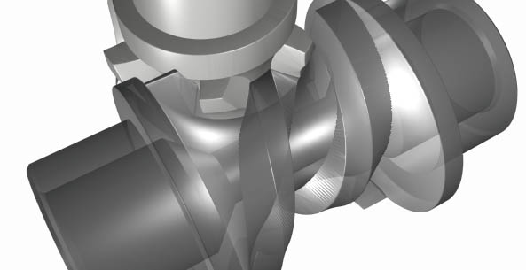 Ultra Globoid Gear set. DDS method works similar for different gear forms. This is an example a practical application. The computer program generates an IGES file of this exotic gear including contact and sliding simulation for misalign gears.
 Novikov gear and pinion tooth in contact. The contact pattern and sliding vectors are rendered on a gear tooth and the pinion tooth surface is in wire frame.
 Spiral Bevel tooth.
AVI animation 0.4Mb.
Spiral Bevel tooth.
AVI animation 0.4Mb.
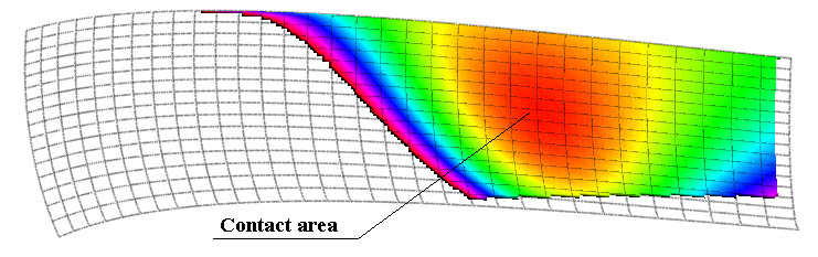
 Helical tooth contact. Output form DDS based software. It shows the gear and pinion teeth with contact pattern rendered on the gear tooth surface.
 WN Novikov tooth contact. Output form DDS based software. It shows the gear and pinion teeth with contact pattern rendered on the gear tooth surface.
AVI animation 0.4Mb.
WN Novikov tooth contact. Output form DDS based software. It shows the gear and pinion teeth with contact pattern rendered on the gear tooth surface.
AVI animation 0.4Mb.
 Double WN Novikov tooth contact. The DDS method can simulate the contact between anything. This example show what we have by inputting double Novikov tooth form in our program.
 Hypoid pinion tooth. The Hypoid gear is common in automotive. There is still question how to increase the driving efficiency of hypoid gear. The DDS efficiency simulation can help. The efficiency of different designs would be very small to identify in experiment. It will be also expensive. The computer program for integrated efficiency simulation would allow to see very small efficiency improvement.
 Double Novikov mesh.
 Novikov mesh.
 Palloid gear set.
 Tooth contact under load. The accurate stress analyze is possible because of the very high geometrical resolution of the DDS method.
 Double Novikov contact on helical gear. Ideal profiles: same radiuses.
 WN Novikov contact on helical gear. Ideal: same radiuses.
AVI animation 0.5Mb.
WN Novikov contact on helical gear. Ideal: same radiuses.
AVI animation 0.5Mb.
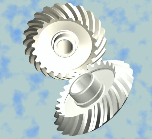
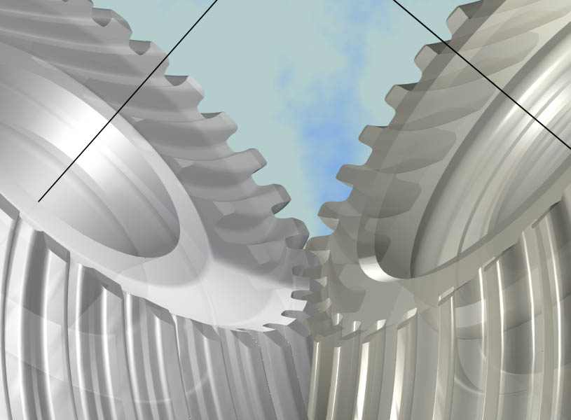 Nice gear set. It is really looking nice. It is nice for presentation and for understanding as well. The modern technology provides nice tools for designer. One example is CAD. Another example is DDS. With CAD and DDS an engineer can see much more that on a drawing board.
 Novikov gear tooth.
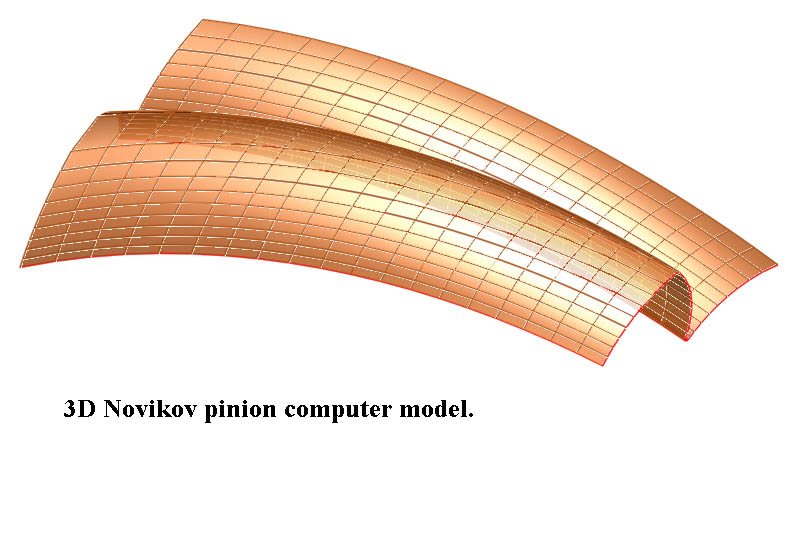 Novikov pinion tooth.
 3-d cutting simulation.
 3-d cutting simulation.
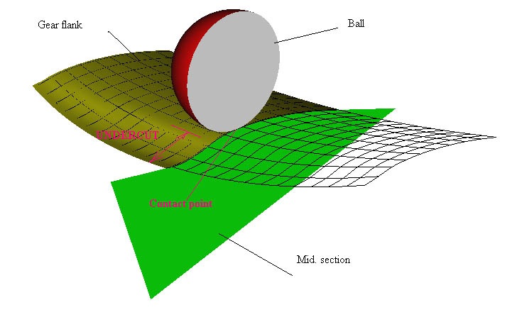 Ball and undercut on gear tooth.
 Hyperbolic gear. DDS gives a freedom for imagination. Before DDS one would spend a life to design, make and test a new idea. DDS does is all fast, accurate and nice looking. The hyperbolic gear would be complex to make in real life. DDS makes the hyperbolic gear as a computer file. It puts it in contact and generates efficiency and load capacity. Ii is easy to change design parameters and make a number of virtual test to optimize the design. Then a real prototype can be manufactured from a CAD file on a low cost CNC equipment.