NEW DISCOVERIES IN WN GEAR GEOMETRY.
Dr. Stepan V. Lunin. 2001
A common mistake in understanding of (Wildhaver-Novikov)WN gears was discovered by using a new numerical method for computerized simulation of gear geometry. The correct form of WN tooth contact can be simulated with the new computational method. New discoveries explain why WN geometry can not provide significant increase of the gear strength. However, some load capacity increase can be achieved by optimizing WN gear design with a help of the universal gear modeling method. Practical examples of computerized WN simulations and improvements on real gears are presented.
Picture 1. 3-dimentional model of Wildhaver-Novikov gear mesh.
The previous research of WN gears was based on a flat representation of the tooth contact and could not provide a correct understanding of the complex tooth geometry (Picture 2).
Picture 2. 2-dimentional understanding of of WN gears. Faydor L. Litvin, Pin-Hao Feng, and Sergei A. Lagutin "Computerized Generation and Simulation of Meshing and Contact of New Type of Novikov-Wildhaber Helical Gears" NASA CR-2000-209415 ARL-CR-428, October 2000, page 17.
Unfortunately experimental results did not meet high expectations in improvement of WN gear strength. The common explanation for low-test results was a high sensitivity of WN gears for the center distance variation. New experiments were conducted on WN gears manufactured with high level of accuracy, but the gear strength remained low.
The computerized 3D-gear simulation method developed by the author in 1984 adds another dimension to the well-known drawing of the WN gears (Picture 3).
Picture 3. 3-dimentional simulation of WN contact.
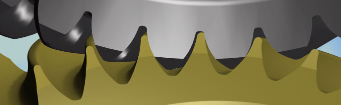
The universal computerized method provides detailed output for the WN geometry and tooth contact. The gear tooth surfaces are generated in high resolution (Picture 4-6).
Picture 4. High resolution of WN mesh simulation.
Picture 5. WN gear model.
Picture 6. WN pinion model.
Adding the third dimension to the tooth contact picture allows to do an accurate comparison of the tooth contact area on involute and WN gears. The comparison calculation shows that the total area of WN contact can be larger than on similar size involute contact. However the differences in the calculated contact stresses on WN and involute gears is not as large as was predicted before (Picture 7).
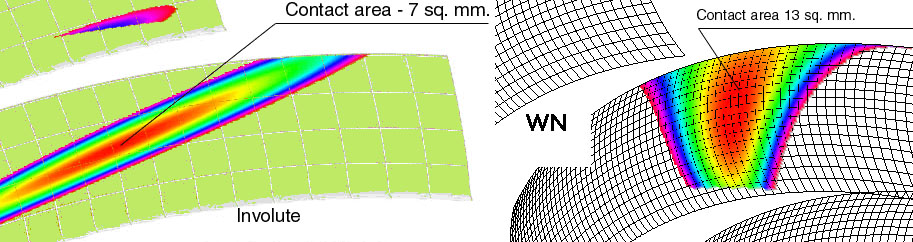
Picture 7. Comparison of the contact area for similar size WN and involute gears.
The new 3-d modeling method was used for calculation of the contact area for the WN gears during the rotation. The method calculates the area of the contact for all the participating teeth in the mesh (Picture 8-9).
Picture 8. Visualization of the tooth contact on all the teeth in the mesh on WN gear.
Download AVI animation 320 Kb.
Picture 9. Visualization of the tooth contact on all the teeth in the mesh on involute gear.
Download AVI animation 240 Kb.
The total area of the WN contact was calculated during rotational simulation. The contact area is calculated for all the tooth in the mesh. The total area of the contact shows a high variation during the gear rotation (Picture 10).
Picture 10. Variation of the total contact area on rotating WN gears.
The total contact area on WN gear repeatedly reaches its maximum and minimum during rotation. The minimum value of the contact area has to be taken into account for the contact stress evaluation. The calculation of the total contact area was calculated for involute tooth as well. It was discovered that the total minimum contact area on WN gears could be even lower than on involute gears. It is desirable to increase the minimum drop of the total contact area on WN in order to decrease contact stress. The contact simulation was conducted for different design parameters such of number of teeth and helix angle. The accurate contact simulation shows possibility to gain only a small improvement of the contact on WN gears. With optimized design parameters the total contact area on WN gears can be larger than on involute gears for 20-50%. The calculation of the total contact area was done for different helix angles for WN gear (Picture 11). The optimized WN design has highest value of minimum drops on the contact area variation curve.
Picture 11. Total contact area of WN gear for different helix angle.
This accurate 3-d simulation of the contact area can explain poor experimental results on WN gears. The total contact area calculated on all the meshing teeth of WN gears changes very much during rotation. The gears experience the highest stresses when the total contact area is smallest. Unfortunately the accurate 3-d modeling tool was not available before. It was impossible to predict the correct picture of the contacting teeth. However the contact stresses on WN gear can be lower when the design parameters are optimized with an accurate 3-d modeling tool developed by the author.
The shape of the tooth contact on WN gear is also misunderstood. It is a common mistaken to describe the contact area of the WN gear as ellipse (Picture 12).
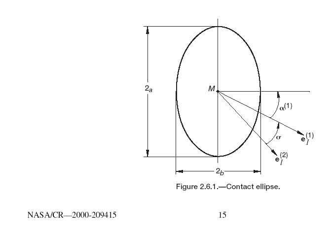
Picture 12. Elliptical form of WN tooth contact reported by NASA. Faydor L. Litvin, Pin-Hao Feng, and Sergei A. Lagutin "Computerized Generation and Simulation of Meshing and Contact of New Type of Novikov-Wildhaber Helical Gears" NASA CR-2000-209415 ARL-CR-428, October 2000, page 15.
The accurate 3-d simulation can address to the misleading usage of geometrical terminology for describing of a 3-dimentional domain by using word ellipse. Calling the contact area by the name of a flat geometrical figure was appropriate for somebody unfamiliar with benefits of 3-d computer graphics. The author presents an accurate 3-d contact simulation of the WN contact (Picture 13).
Picture 13. Correct 3-d visualization of WN tooth contact.
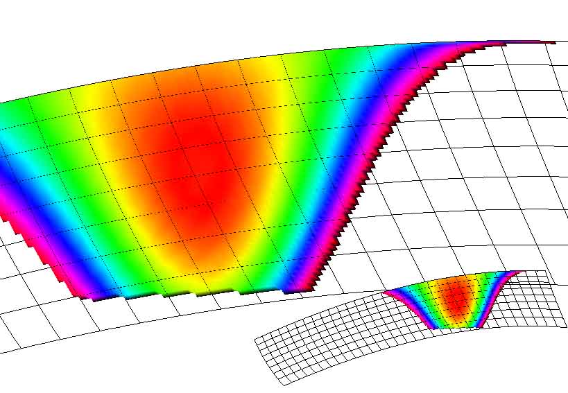
Using word ellipse for describing of the WN contact misleads a researcher from the understanding of the real physical nature of the contact form. As it can be seen from the correct visualization the image of WN contact area has 3 axis. (Picture 14.)
Picture 14. Three axis of the contact pattern discovered by the author on WN gears.
The discovery of the three axes on WN contact gives a guideline for design of optimized high load WN gears. The new 3-d computerized method was used for simulation of the WN contact for different design parameters.
The difference of radiuses of the concave profile of WN gear and convex profile of WN pinion determines the shape and the size of the contact pattern. (Picture 15.)
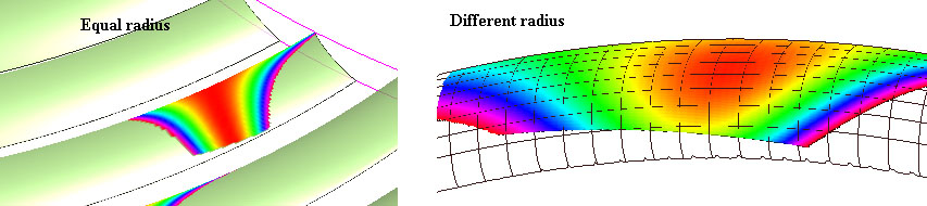
Picture 15. Different contact forms for different radiuses of WN profiles.
The contact area becomes larger with smaller difference in radiuses of contacting surfaces. The contact area is not equally distributed along the tooth height. The larger portion of the contact is located on the upper portion of the concave tooth and on the lower portion of the convex tooth. The large difference of the radiuses on the contacting profiles may decrease the contact area very much, because of the not elliptical form of the contact area. The contact area has its maximum width located off the middle of the theoretical contact. (Picture 16).
Picture 16. Off set of the maximum width of the contact.
The discovered offset of the middle of the contact from the calculated theoretical position has to be taken in to account during the gear design. A practical recommendation would be to offset the concave gear tooth out and convex gear tooth in to the center to correspond with the offset of the real contact pattern form. The amount of the offsets can be calculated exactly on 3-d simulation software.
Helix angle changes the length of the contact. (Picture 17).
Picture 17. WN contact for different helix angle.
The lower helix angle provides a larger contact area and lower stress. However lowering of the helix angle decreases contact ratio. The new 3-d computerized method helps to find an optimal value of the helix angle that provides the maximum contact area on all participating teeth.
CONCLUSION.
Correct 3-d numerical method of gear geometry simulation was applied to WN gear tooth geometry. It was discovered that the correct form of the WN tooth contact is different from how it was described before. The correct calculation of the WN tooth contact explains why the strength of WN gears is not as high as it was predicted by the most of the researchers. The new numerical gear simulation method has been tested and approved for detailed analyses of 3-dimentional complex geometry of WN gears. 40%-60% increase of the load capacity of WN gears can be achieved by optimizing the tooth geometry with a help of the new numerical method.