We sale variable ratio rack and pinion design since 1999.
Variable ratio rack and pinion set is commonly used for steering systems on automobiles. Rack tooth surface has to be adjusted in order to achieve variable ratio. Unfortunately, none of existing engineering books provide algorithm for mathematical calculation of the vr-rack tooth surface. Nether gear generating machines exist for generating vr-racks. Complicated software is required to calculate tooth geometry on vr-rack. We have information about only five existing software tool for vr-rack tooth geometry calculation: one from Australia from the original inventor of vr-rack, one from Germany (ZF), and three from General Motors in the US. The currently most advanced and the most accurate software is the one that we have developed for Saginaw Steering System (former Delphi division of GM) in 2001. From our customerĺs comments we understand that our software produces the most accurate rack tooth form. The advantage of our software is also capabilities to generate vr-rack tooth forms to mesh correctly with modified (not involute) pinion. While our software has been used for generating of the traditional vr-racks since 1999 this article describes advanced options with tooth profile modification that has not been widely used yet, but also available.
Abstract
Existing variable ratio rack and pinion drives are limited in the amount of variable ratio change along the rack. Higher gain of the ratio is required for advanced application on racing cars, such as FORMULA ONE, and on aerospace applications, such as High Lift flight control system or landing gears. The authors have applied Direct Digital Simulation (DDS) method for 3-dimentional modeling of variable ratio rack geometry. Not involute tooth form has been considered for improving of variable ratio rack. The high resolutions CAD models of different samples are presented, including Double Novikov, tooth design. The calculation results show advantages of DDS method for simulation of variable ratio rack geometry with not involute tooth profile. Practical vr-rack simulation software has been developed.
1. INTRODUCTION
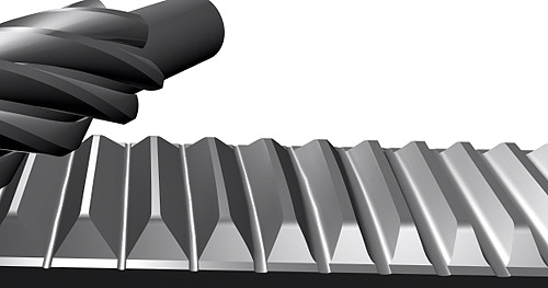
Variable ratio racks (vr-rack) are used in automotive steering systems and in aerospace linear actuators. Figure 1.
Figure 1. 3-dimentional CAD model of vr-rack.
VR-rack has become a common component of an automotive steering system. Variable ratio provides optimized steering performance by making the steering system less sensitive while driving straight and more sensitive while making turns. Figure 2.
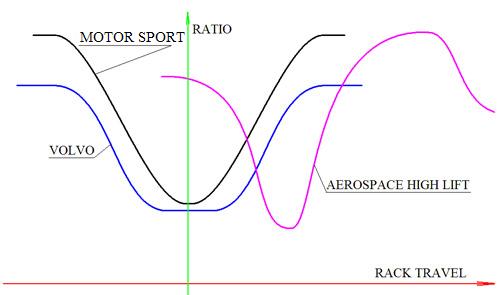
Figure 2. Variable ratio gain versus steering angle for a typical steering system.
Vr-racks have been adopted on consumerĺs cars and on racing cars. Formula One racing teams have been taking advantage of using vr-racks for improved control on high speed and on sharp turns. A racing car normally requires more sensitive steering system compare to an average consumer car. On a racing car the steering wheel rotates for a smaller angle in order to provide the same turning effect. Higher sensitivity requirements demand more aggressive ratio gain on vr-rack. Practically, higher ratio gain is better for a racing car. High ratio gain is also in demand in aerospace mechanical systems used for secondary flight controls like High Lift systems incorporated flaps on the trailing edge and slots on the leading edge of a wing. Krueger leading edge actuators can benefit in variable ratio in particular due to high variation of the load during deployment. Figure 3.
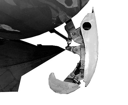
Figure 3. Variable camber Krueger actuator.
The authors have conducted investigation of non-traditional tooth geometry in comparison with the traditional involute. Involute tooth form has its limits in providing high ratio gain on demanding automotive and aerospace applications. It becomes impossible to achieve a conjugated mesh between the involute pinion and vr-rack for high ratio gain because of increased areas of undercut on the vr-rack tooth. Figure 4.
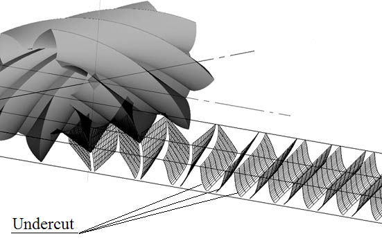
Figure 4. Unacceptable increase of undercut area on the vr-rack tooth generated by an involute pinion with high ratio gain.
Modification of the involute tooth profile and use of not involute tooth forms extends flexibility in design of extreme vr-racks. Figure 5.
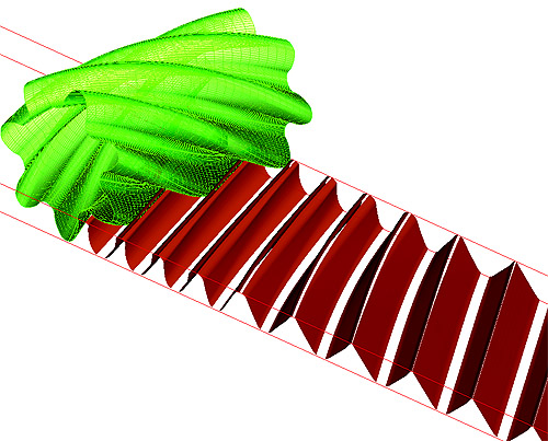
Figure 5. Double Circular (DC) tooth profile.
The existing production methods of vr-racks and pinions are very capable of producing any tooth forms. Practically the manufacturing process for the vr-rack is the same for involute and for not involute tooth form because the vr-racks are produced by forging, EDM or single-point milling. Manufacturing of the not involute pinion may be some more expensive because of slightly higher cost of not involute cutting tools. But in a high production values the higher cost of the cutters is offset by increasing life of the cutters and reducing requirement for the accuracy of the finished parts. Modern manufacturing capabilities do not limit the geometry of the vr-rack or the pinion tooth. However, the existing limitations of the Theory of Gearing [1] do not provide a practical theoretical solution for manufacturing of vr-racks of different geometry. Direct Digital Simulation (DDS) method [2][3] makes it possible to create mathematical models of different gears including mathematical model of vr-rack with not traditional tooth form. Traditional vr-rack software limits designers by involute tooth profile.
DDS method has been applied for digital simulation of tooth generating action on a vr-rack. Unlike the traditional method, DDS method allows to use arbitrary curve as the generating tooth profile to generate a vr-rack. Practical software packages have been developed and successfully employed in mass production. Advanced graphical 3-dimentional graphical user interface has been introduced for the first for vr-rack design, which allowed improvement of geometry analyses on the design and product development stage of vr-rack. Figure 6.
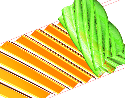
Figure 6. Output of 3-dimentional of vr-rack geometry.
DDS vr-rack software-products have been tested in process of design and manufacturing of vr-racks for Formula-I racing cars, for consumer cars, and for aerospace applications.
Direct Digital Simulation (DDS) method has been practically used since 1986 for automotive, aerospace and marine applications. In 1986 DDS method has been adopted for design and development of Double Circular (DC) helical gears improvement of power to weight ration on MI-28 helicopter transmission. Figure 7.
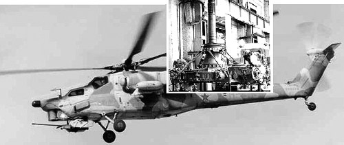
Figure 7. Mi-28 Havoc Attack Helicopter.
At Mil Helicopter DDS method has been practically adopted for developing of simulation software with graphical visualization of non-involute tooth contact pattern. Non conforming tooth profiles have been recognized to have some advantages in performance. However, not they did find many practical applications due to sensitivity to the center distance Figure 8. Vr-rack is sensitive for center distance even if the has the traditional involute tooth form. Because of its sensitivity, involute vr-rack looses its single advantage to a not involute vr-rack. Using the DC tooth geometry on vr-rack can provide the same advantage as on helicopter gears. More specifically DC gears may provide quieter operation and lover variation of the backlash.
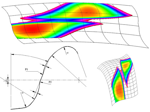
Figure 8. 3-d visualization of not involute tooth contact used at MIL Helicopter in 1986.
DDS method has proved to be a low cost and effective method for digital simulation of the tooth geometry and for 3-dimentional tooth contact analyses of complex helicopter gear systems. The main advantage of DDS versus the traditional method is increased visualization capability that helps to present the gear tooth contact at high level of details. Figure 9.
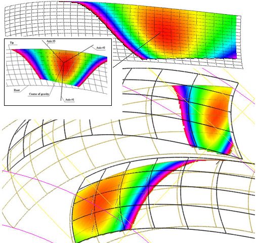
Figure 9. DDS visualization of Novikov tooth contact.
DDS has been used for development of a worm face gear drive. The high level of details that can be obtained from DDS method had helped to design and propose a low cost alternative to a hypoid drive axle gear. [4] Figure 10.
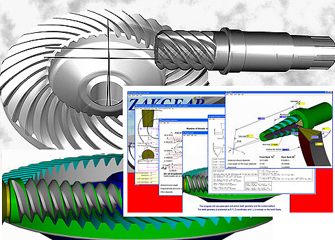
Figure 10. DDS digital model of a worm face gear.
In the United States DDS method has been promoted by ZAKGEAR [5] for automotive, marine and aerospace application since 1996. ZAKGEAR has developed several custom software packages for different applications including spiral bevel and hypoid gear simulation software. Figure 11.
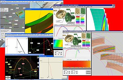
Figure 11. Example of 3-dimentional output of DDS spiral bevel and hypoid gear software.
Direct Digital Simulation (DDS) is a straightforward method of modeling, which is based on mathematical representation of subtracting one object, the tool, out of another, the work part. [5] Figure 12. The key difference between DDS and the Theory of Gearing is that DDS is not using elements of differential geometry. The underlying engineering idea of DDS algorithm is more similar to the methods used in developing of solid modeling CAD software products. The difference between DDS and the standard CAD product is that DDS has a higher level of optimization in the algorithms, which are used for simulation of the tool pass.
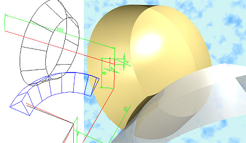
Figure 12. Graphical presentation of DDS application to spiral bevel gear cutting.
Simplified DDS operations can be performed on standard CAD software like AutoCAD, Unigraphics, or Pro/Engineer. Standard CAD software has capability of simplified programming. Below is an example of AutoLISP program that can be used in AutoCAD for DDS generation of a true spiral bevel or hypoid gear.
(defun G()
(setq dt (* dfi al))
(setq x 0.0)
(getreal "stop")
(setq i 0)
(while (< x pi)
(setq i (+ i 1))
(command "copy" sb "" (list 0 0) (list 0 0))
(command "subtract" gear "" (entlast) "")
;;; rotate the cutter
(command "rotate" sb "" (list 0 0) (list (cos dt) (sin dt)))
;;; rotate the gear
(command "ucs" "ob" axis)
(command "ucs" "y" 90)
(command "rotate" gear "" (list 0.0 0.0) (list (cos dfi) (sin dfi)))
(command "ucs" "w")
(setq x (+ x dfi))
)
)
While simplified simulations can be done on standard CAD software, advanced DDS algorithms provide critical features that can not be achieved on standard CAD programs. Recently delivered DDS software is capable of 3-dimentional simulation of tooth contact, sliding velocities contact pressure and as the result DDS is capable of accurate simulation of driving efficiency. The main advantage of the method is an optimized mathematical algorithm for more productive, more accurate and faster calculation. In result, DDS software can offer higher resolution and more accurate calculation results compare to other software products. Figure 13.
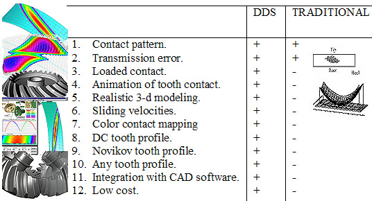
Figure 13. Comparison of ZAKGEAR calculation results versus traditionally used software for spiral bevel gear tooth contact analyses (TCA).
Because of its high resolution capability DDS method helps making discoveries that could not be done without DDS. For example, DDS has been used for simulation of extremely high-resolution 3-d-tooth contact of Novikov vr-rack. It has been discovered that the form of Novikov tooth contact is different from what it was predicted before. Figure 14.
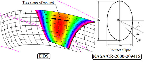
Figure 14. DDS high-resolution 3-dimentional calculation of Novikov tooth contact compare to theoretical prediction based on the traditional theory.
The discovery of the real form of Novikov tooth contact provided a clue how to increase the load capacity of Novikov gears and on vr-ratio racks with Novikov tooth form. It has been discovered that increasing of the profile modification of Novikov gear reduces the contact area more than it was predicted by the classic gear theory, which was traditionally based on the assumption of the contact ellipse. Accurate and high-resolution digital models helped to find a solution for design improvement of Novikov gears so the valuable contact area will not be lost by the excessive profile modification. DDS has offered an easy to understand visuals explanation of advantaged of Double Contact (DC) Novikov tooth form versus traditional single contact form. Figure 15.
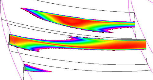
Figure 15. DDS model of contact on DC tooth profile. Standard DC profile by Russian GOST standard is used.
3. Applying Direct Digital Simulation (DDS) for variable ratio vr-rack.
Using DDS for vr-rack has become critical due to high requirements to accuracy and manufacturability of the vr-racks. The one of disadvantages of the traditional vr-rack software is failure to simulate the correct form of root fillet, which is generated by the tip of the generating pinion. Figure 16.
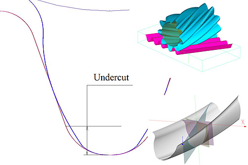
Figure 16. Tip of the generating pinion produces an undercut fillet area at the root of the vr-rack tooth.
While the classic gear theory provides a formulated solution for a simple undercut curvature, it fails in comparison with DDS if the generation curvature gets more complex than a simple circle. DDS is capable to generate the undercut in 3-dimensinal space for an arbitrary generating surface. DDS software solves the problem of using complex generating profiles, such as generated fillets on the root and on the tip of the generating pinion. With traditional methods it is difficult if not impossible to calculate the vr-rack tooth surface if arbitrary pinion tooth geometry is used.
Because of the limitations of the traditional software the root fillet curve in many practical designs is replaced by a simple circle. It results in reduction of active tooth profile and increased clearance requirements.
But the more important limitation of the traditional calculation method is its inability to generate vr-rack geometry using a not involute tooth form. Not involute tooth forms have shown advantages in noise and load capacity. The traditional design practices limit the opportunity to design high performance and lower cost vr-racks. DDS method is more capable, more flexible and, it has been proved to design a higher performance steering racks for Formula One cars. The advantages of DDS method for vr-rack design are:
The authors have been delivered several DDS software products including software for vr-rack which also includes capability to simulate the dynamic tooth contact and in result, to analyze driving efficiency for different tooth forms. It has been found that Double Circular (DC) tooth form provides significantly reduced noise and reduced deflection of the rack due to lowered, up to 10 degrees or less, pressure angle at the pitch point of the tooth contact. The naturally rounded tip and the root of the DC tooth reduce the undercut areas and in addition it improve forging production process. Figure 17.
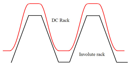
Figure 17. Comparison of DC tooth form and involute tooth form for manufacturability by forging.
It has been noticed that use of nonconforming tooth profile makes vr-rack less sensitive for shaft misalignments. While the contact pattern on DC tooth is still as sensitive to the center distance as for involute tooth, the sensitivity to skew of the pinion axis has been significantly reduced. As the result, the DC tooth form on variable ratio rack allows higher deviations in manufacturing process and it provides quieter and smoother operation of the steering rack and better feel of the steering, which is resulting in added value to the finished product. Reduction of the noise level is a very important factor for consumerĺs cars especially if to take into account cost reduction of the process to produce vr-racks. Figure 18.
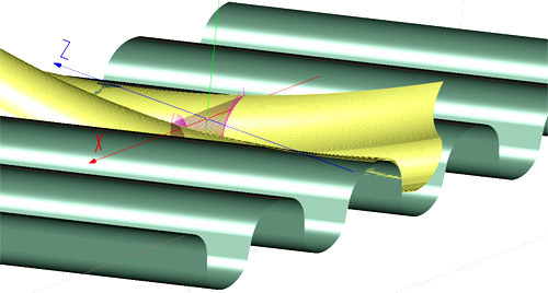
Figure 18. DC vr-ratio rack is more suitable for forging because of round corners and lower requirements for profile accuracy.
4. Conclusion:
Direct Digital Simulation (DDS) method has been practically applied for improving and cost reduction of design and production of variable ratio vr-rack and pinion linear actuators for automotive steering systems and for aerospace applications. With a help of DDS it has become possible to open new opportunity for design of improved vr-racks with not involute or modified involute tooth form because, in many applications, not involute tooth form provides advantages in cost and performance. While not involute tooth form seems to be more complicated in manufacturing of gears it does not apply to manufacturing of vr-racks. In fact, cost of vr-rack with DC tooth form is reduced by advantages of more forgeable tooth geometry and lower requirements to accuracy.
Click here to see a sample of VR-rack design.
Click here to see interactive 3-dimentional model.