
High efficiency and high ratio gear drive.
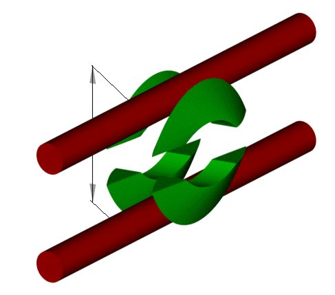
DDS method was used for investigation of the existed gear drive. Face cylindrical worm gear drives have been investigated on DDS computer models. Disadvantages in existed manufacturing and design concepts were found and a new high performance concept has been developed. The new ZAK design has a very solid CAD and mathematical background. Each individual point on tooth surface has been precisely calculated by a unique software. (Click on the following links to see: Animated 3D CAD models of ZAK gear set and contact pattern.)
Existed gear designs and manufacturing processes were simulated as DDS computer models for detailed investigation. ZAK DDS geometry calculation software provides the following options:
- Calculation of 3D geometry of the gear and pinion tooth surface. Generating CAD model for CMM inspection or for injection molding tools machining on CNC
- Computer simulation of the gear mesh with animated contact pattern, sliding velocities and transmission error
- Calculation of the gear cutting tool geometry and gear cutting machine summaries
- Calculation of undercut areas on both flanks on gear and pinion teeth.
- Generation data file for finite element analyses
- Calculation of cutting tools modifications and crowning for localization of the contact pattern
The pictures below are the output of the software integrated with AutoCAD.
The picture is the face view on the gear. White circules are the gear tooth face and the red lines are the generating surface of the cutting tool. The idea of the presentation is to show step by step the manufacturing process of the gears. The red cutter surface moves and the white gear blank rotates.
Each step the red cutter takes some material out of the white gear blank. The same happens during real cutting. The cutter does not have infinite quantity of the cutting blades. Each blade creates a cutting mark. There are the cutting marks on this computer model as well.
The CAD simulation shows undercut areas on the both flanks of the gear. The model on the picture is in weir frame mode so you are looking at the both flanks in the same time.
The manufacturing process for ZAK gears is less expensive because the gears are manufactured on the computer before going to the expensive shop floor. The gears can be cut on a regular gear hobber. The pinion is usually manufactured on a thread grinding machine. Localization of the contact pattern can be done by modified gear cutter or modified pinion thread.
There were nor much of inspection methods before. They could offer only composite rolling inspection. Gear companies not familiar with ZAK digital concept are still offering composite rolling inspection. Modern ZAK concept provider all of the data for individual inspection for each particular gear parameters. Such of possibilities allow to point on a manufacturing problem and precisely correct it. With ZAK DDS digital model the inspection can be done similar to CMM inspection of spiral bevel gears by mapping the tooth surface and correcting machine settings.
Dimension over pins on digital ZAK pinion.
|
ZAK |
Izevsk |
USA, UK, India |
|
|
1. Using DDS for design and manufacturing simulation |
Yes |
- |
- |
|
2. Capability to do 3D gear tooth surface simulation |
Yes |
some |
- |
|
3. Capability to do 3D pinion tooth surface simulation |
Yes |
some |
- |
|
4. Capability to do computerized tooth contact analyses |
Yes |
Yes |
- |
|
5. Capability to predict final tooth surface for given gear cutting machine settings |
Yes |
Yes |
- |
|
6. Avoid gear tooth surface undercut |
Yes |
some |
- |
|
7. Avoid pinion tooth surface undercut |
Yes |
some |
- |
|
8. Calculate undercut area on the pinion active tooth surface |
Yes |
Yes |
- |
|
9. Calculate undercut area on the gear tooth surface |
Yes |
Yes |
- |
|
10. Gear ratio |
Any |
Any |
Up to 400 |
|
11. Back driving |
Yes |
Yes |
Limited |
|
12. Equal driving characteristics in both directions |
Yes |
Yes |
- |
|
13. Equal pressure angle |
Yes |
Yes |
- |
|
14. 3D model of molding tools |
Yes |
Limited |
- |
|
15. Adjust to "0" backlash |
Yes |
Yes |
Yes |
|
16. Transmit high power |
Yes |
Yes |
declared |
|
17. Availability of design and manufacturing information. |
Available |
Yes |
limited |
|
18. 3D computer model |
- |
- |
|
|
19. Localization of the contact pattern |
Yes |
Yes |
- |
|
20. CMM inspection |
Yes |
Some |
- |
|
21. Equal driving efficiency in both directions |
Yes |
Yes |
- |
|
22. Simple rolling test |
Yes |
Yes |
Yes |
|
23. Pinion lead inspection |
Yes |
some |
- |
|
24. Pinion tooth profile inspection |
Yes |
- |
- |
|
25. Pinion spacing inspection |
Yes |
Yes |
- |
|
26. Pinion and gear run-out inspection |
Yes |
Yes |
Yes |
|
27. Pinion normal and axial CMM tooth thickness inspection |
Yes |
- |
- |
|
28. Gear normal and axial CMM tooth thickness inspection |
Yes |
- |
- |
|
29. Composite single flank inspection |
Yes |
Limited |
Yes |
The following statements make us feel very sceptical about capabilities of some companies to manufacture a good gear product:
1. The owersized gear cutter can be used for better contact pattern development but we can not show it on a computer model.
2. The undercut does not exist on the gear and pinion surfaces or it is so small so we do not need to know how to calculate it.
3. We do not need DDS computer gear modeling methods for tooth geometry simulation because tens of years of experience.
4. The gears are stronger but we can not create a computer model to proof it by FEA.
5. We do not use CMM inspection of the gear and pinion tooth surface. We inspect the mesh on a rolling tester.
For gear cutting tool information visit: 
Download computer gear animation for the gear above. (4.5Mb)
Compliments from: Dr. ZAK
For comments contact: zak@zakgear.com