Correct 3d models of spur and helical gear tooth for $245.00

Best Titanium Lug Nuts and Bolts
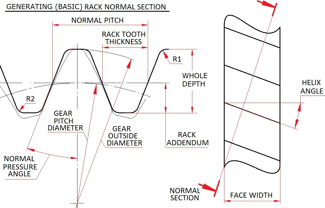
How to make correct 3d CAD models of helical and spur gears on YouTube video channel: "spiralbevel".
Our software generates gear tooth surface identical to what would be cut on a real gear cutting machine if the input data were used in hob cutter design. After receiving you order we validate the input data for errors, visualize 3 dimensional model of the gear tooth from your data, examine the 3d model, recalculate the 3d model for additional accuracy, and, produce IGES file of the tooth surface including the root area (undercut) for delivery.

Basic rack input data


Download samples of delivery:
Sample helical tooth surface flank 1 in IGES
Sample helical tooth surface flank 2 in IGES

Input data into “Buy Now” box.
A – Normal Pressure Angle. For example: 20
P – Normal Pitch. For example: 5.3493
R1 - For example: 0
R2 – For example: <1.072>
T – Rack tooth thickness .For example: 1.2341
D – Rack Addendum .For example: 1.1781
WD – Whole Depth. For example: 3.975
HA – Helix Angle. For example: 20
R/L – Right or Left hand. For example: R
W – Face Width. For example: 25
N – Number of teeth. For example: 8
OD – Gear Outside Diameter. For example: 20.09
Sample input: 20_5.3493_0_1.072_1.2341_1.1781_3.975_20_R_25_8_20.09
A_P_R1_R2_T_D_WD_HA_R/L_W_N_OD

Home page.